 |
MODEL CONSTRUCTION |
| I decided to replace this page - which originally was designed to showcase construction details of various guillotine models - with a step by step pictorial guide to building a guillotine model. I have spent many years teaching myself techniques used in model building and think such information might be useful to those who buy a set of plans of the 1889 guillotine from this site. I elected the 1/6 scale Berger guillotine to be the object of this section as it is, by far, the most popular model I sell and also the one that I have spent the most time perfecting. |
| The building of an accurate and dependably functional model must start with the fabrication of the mouton. To be noteworthy a model must be functional and dependably so. The guillotine is a surprisingly accurate device requiring very close tolerances to work. The fit between the mouton and frame tracks is critical and must be held accurate to within 1/2 mm otherwise the machine will not work properly. If the mouton is too loose it will be prone to hanging crooked, jamming and letting the blade impact the spring support bracket at the end of the track. If it is too tight it will be slowed or stopped by friction and will not bounce properly on impact with the spring stops. From this I concluded that it was much easier to fit the post spacing to the mouton than vice versa. In fact the few models that I constructed starting with the frame and trying to make a mouton to fit it never worked very well. The physics of a scale guillotine model are quite interesting. On a 1/6th model the mouton drop height is decreased by 1/6th while its volume is decreased by 1/6 cubed, ie 1/216 so the energy delivered (weight x drop height) is decreased to 1/1296... which means the model is likely to be very, very wimpy. To counteract this I have always elected to go with a solid steel mouton rather than the more accurate wood core/steel plate covered structure. Other critical factors in the mouton fabrication are exactly square corners and parallel sides; round rollers with perfectly centered axles, located exactly at the same depth inside the mouton to insure parallel and equidistant contact surfaces between rollers and tracks. |
 |
 |
 |
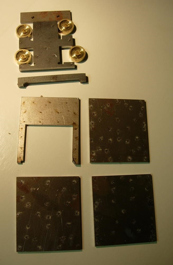
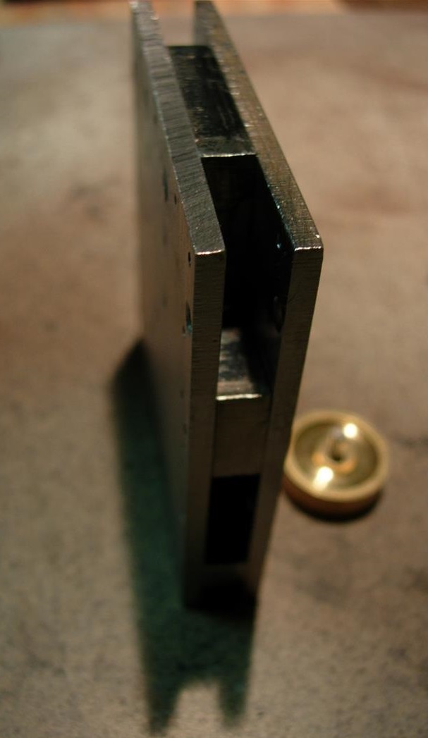
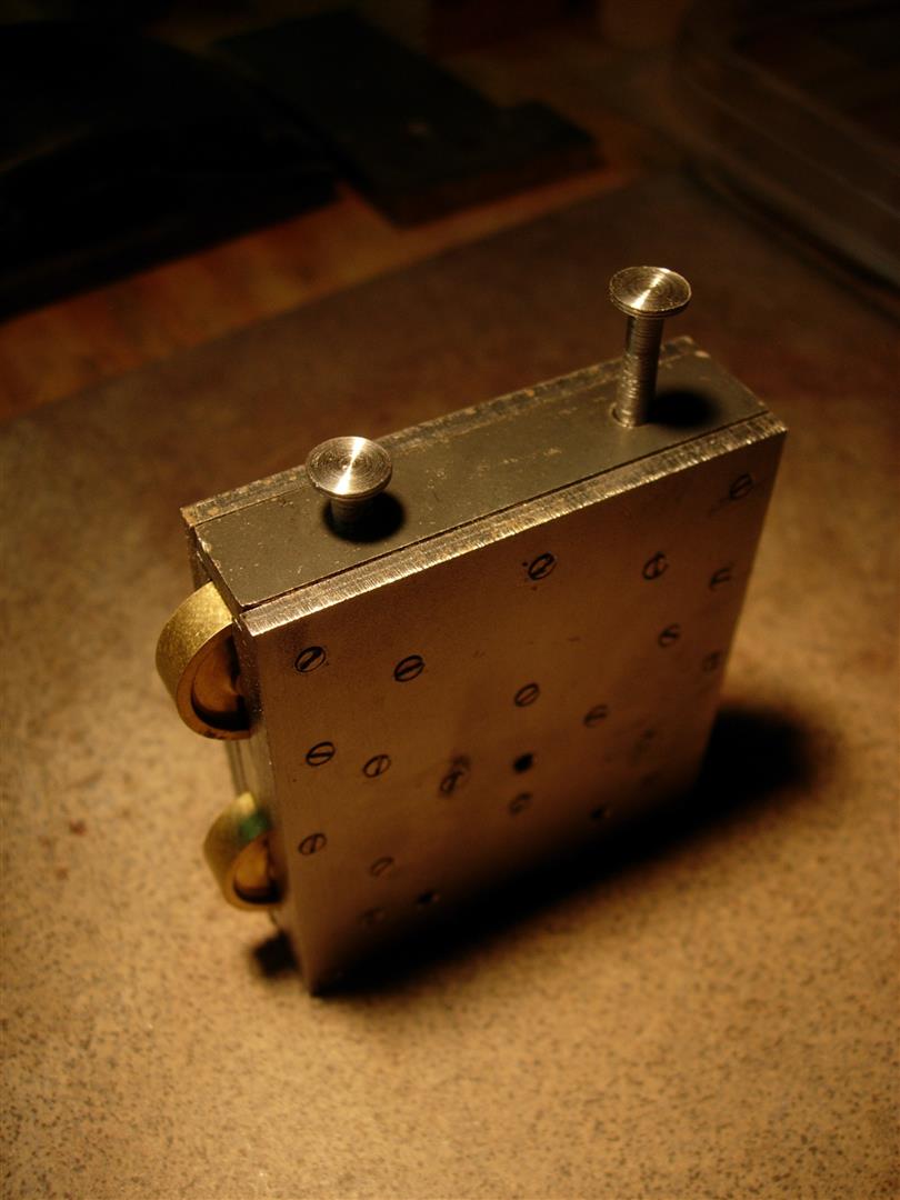
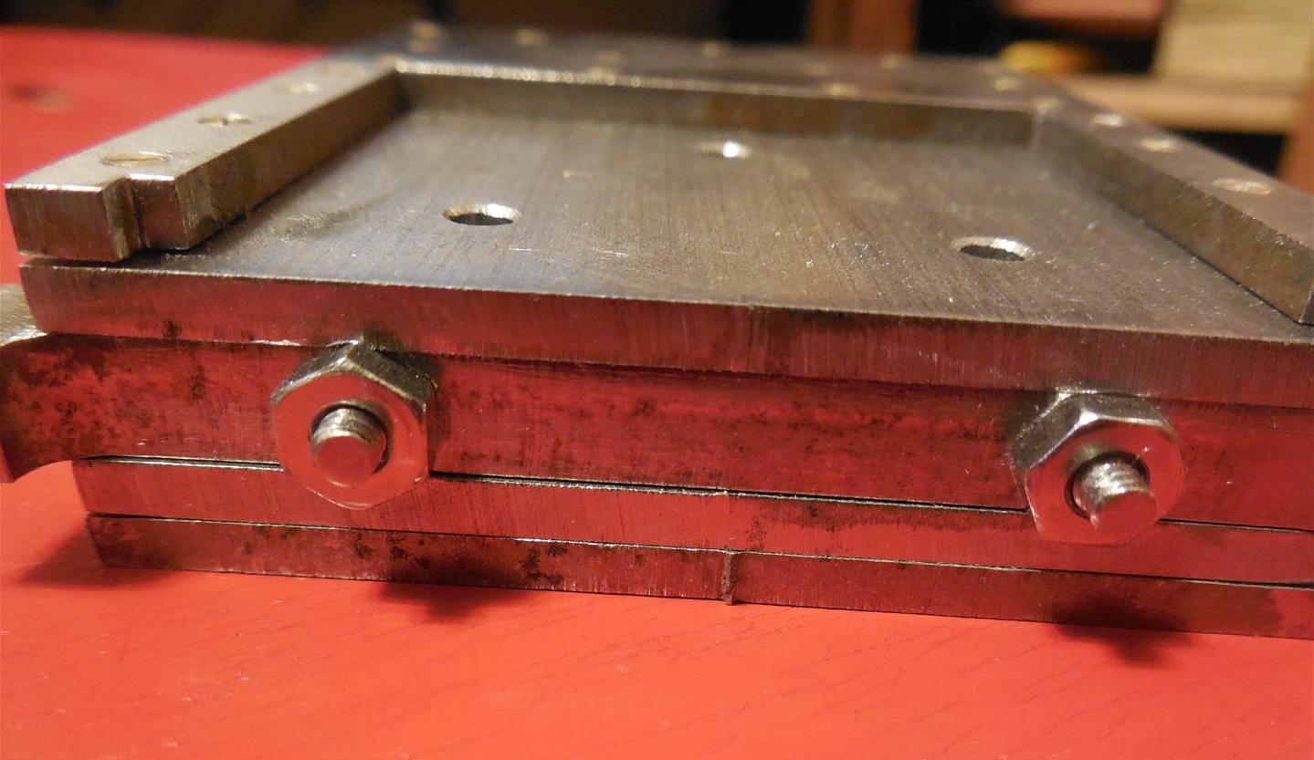
| The photos illustrate some critical aspects of the design of the mouton: Tight clearance, perfectly square angles, all steel construction. I settled on a mouton built from 5 stacked metal plates, four 3mm plates and a 6mm core plate for a total thickness of 18mm. This is slightly off the accurately scaled dimension of 97mm/6 =16.2mm. It might be possible to use a combo of 2mm plates and 3mm plates to get closer to the actual scaled dimension but I opted for the simplicity of using just two plate thicknesses. The 6mm core provides spacing for the rollers and crash bar, the inner 3mm plates hold the roller axles and the outer 3mm plates cover the axle holes and provide the recess cavity for the 3mm thick blade, as well as the front and rear facing for the top cover plate. |
 |
 |
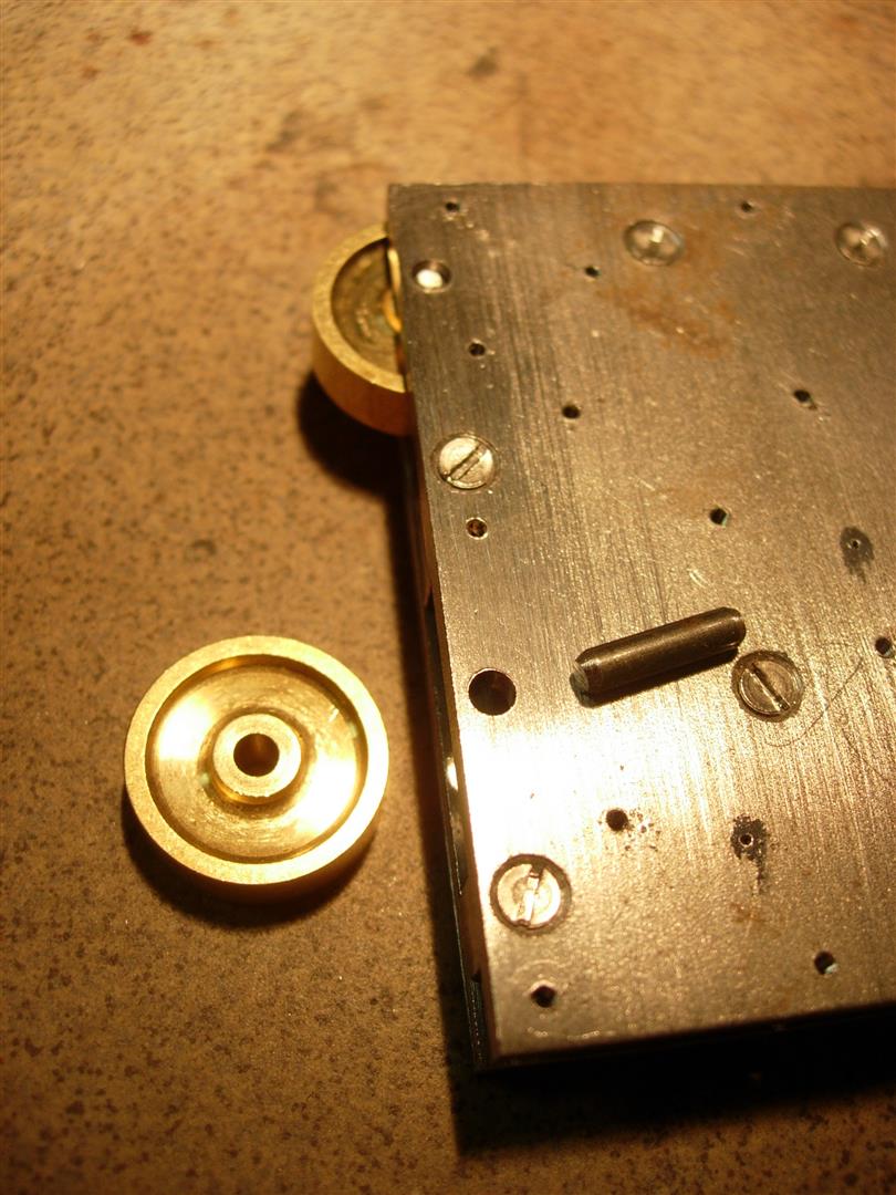 |
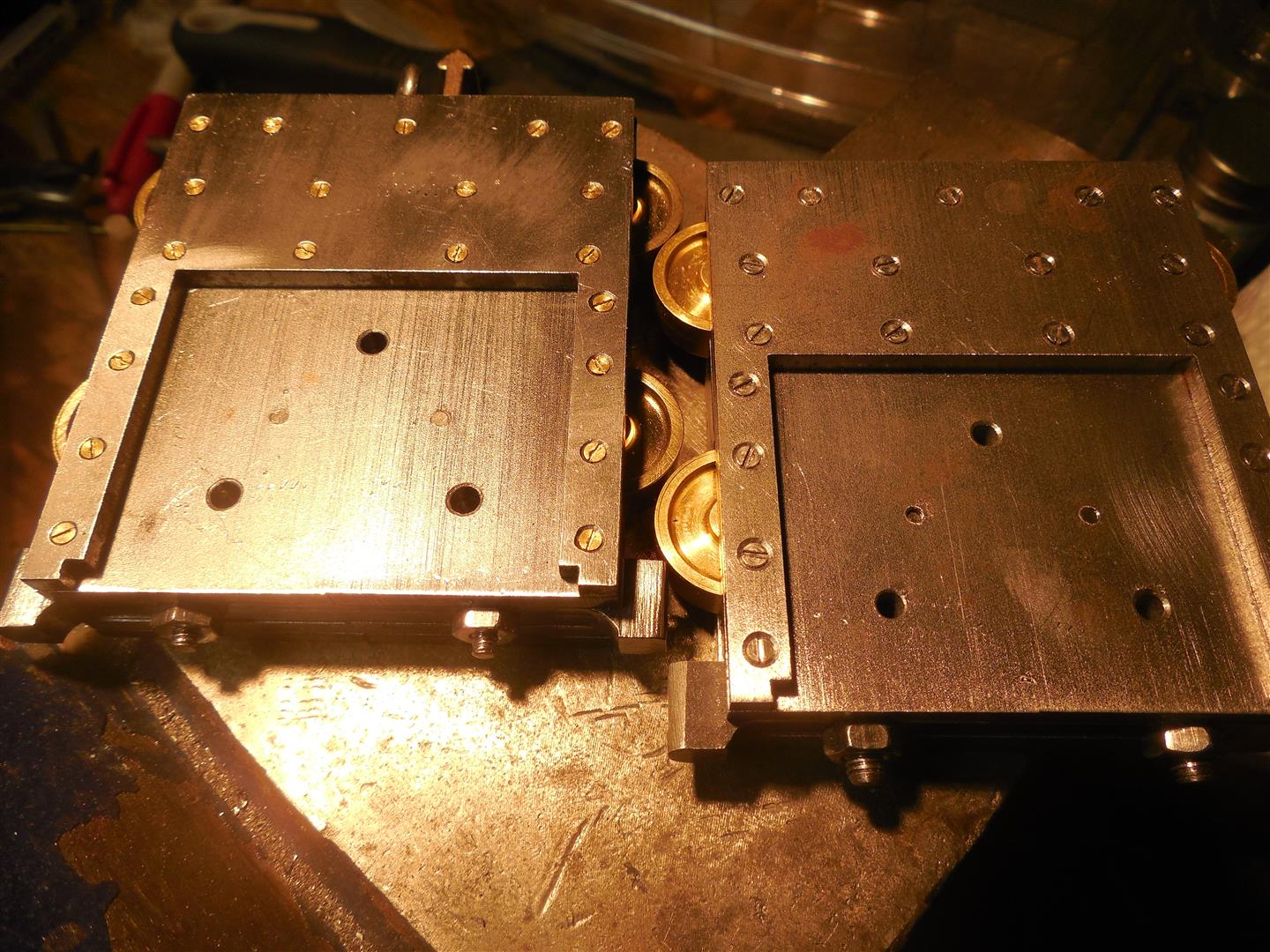
| The core mouton parts are shown above before assembly. The four 3mm plates, the 6mm core, the rollers, the crash bar and the top cover plate. These parts are cut on a computer controlled laser and pilot holes are burned through the plates to insure proper alignment of screws, axles and blade bolts. The three inner plates are assembled using oversized screws (#2-56) which will not be visible from the outside. Roller axle holes are drilled out after plate assembly to insure perfect axle alignment. Short steel axles are fabricated and inserted through the support plates and rollers. These rollers are brass and manufactured on a CNC lathe. This became necessary after cast bronze and hand-machined rollers proved too imprecise, jamming against the mouton slot walls and causing mouton wobble due to irregular diameter and not perfectly perpendicular axles. |
 |
 |
 |
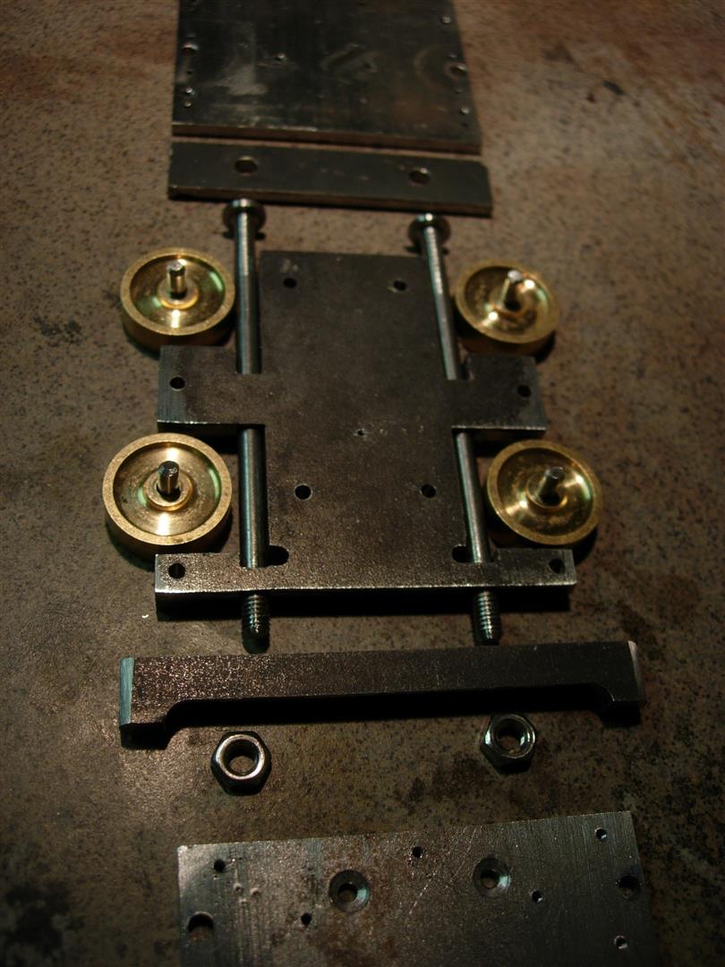
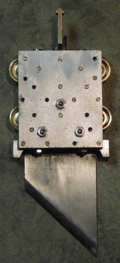
| Two vertical tension rods connect the top cover plate to the crash bar under the mouton. The rod pass in the narrow slot between the blade bolts and the rollers. I use large nails as raw material to make the rods. I machine the nail head and stem on a lathe to get the proper diameter. I thread the end to accept a #4-40 or M4 metric nut. |
 |
 |
 |
| The two outer plates cover the inner plates and block the ends of the roller shafts. Since the screws on these are visible it is important to match the location and size of the original screws as close as possible. This presents a special challenge as the original screws used on the mouton are small and scaling them down to 1/6th size results in some of the smallest hardware available anywhere. Tapping steel plates to accomodate these screws is nearly impossible. I gradually worked the size of these screws down from #1-72 to #0-80 to #00-90. The photo on the left shows the tapping tool I built to make the #00-90 threads. The proper size would probably be closer to #000-120 but so far I have not been able to tap steel plate for this size screws. The taps are very fragile and break too easily. Photo in the center shows the size of #0-80 and #00-90 screws. |
 |
 |
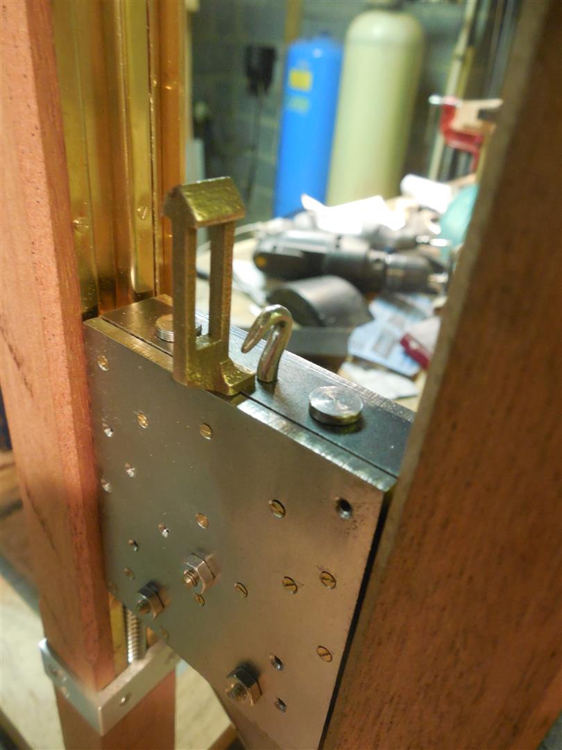 |
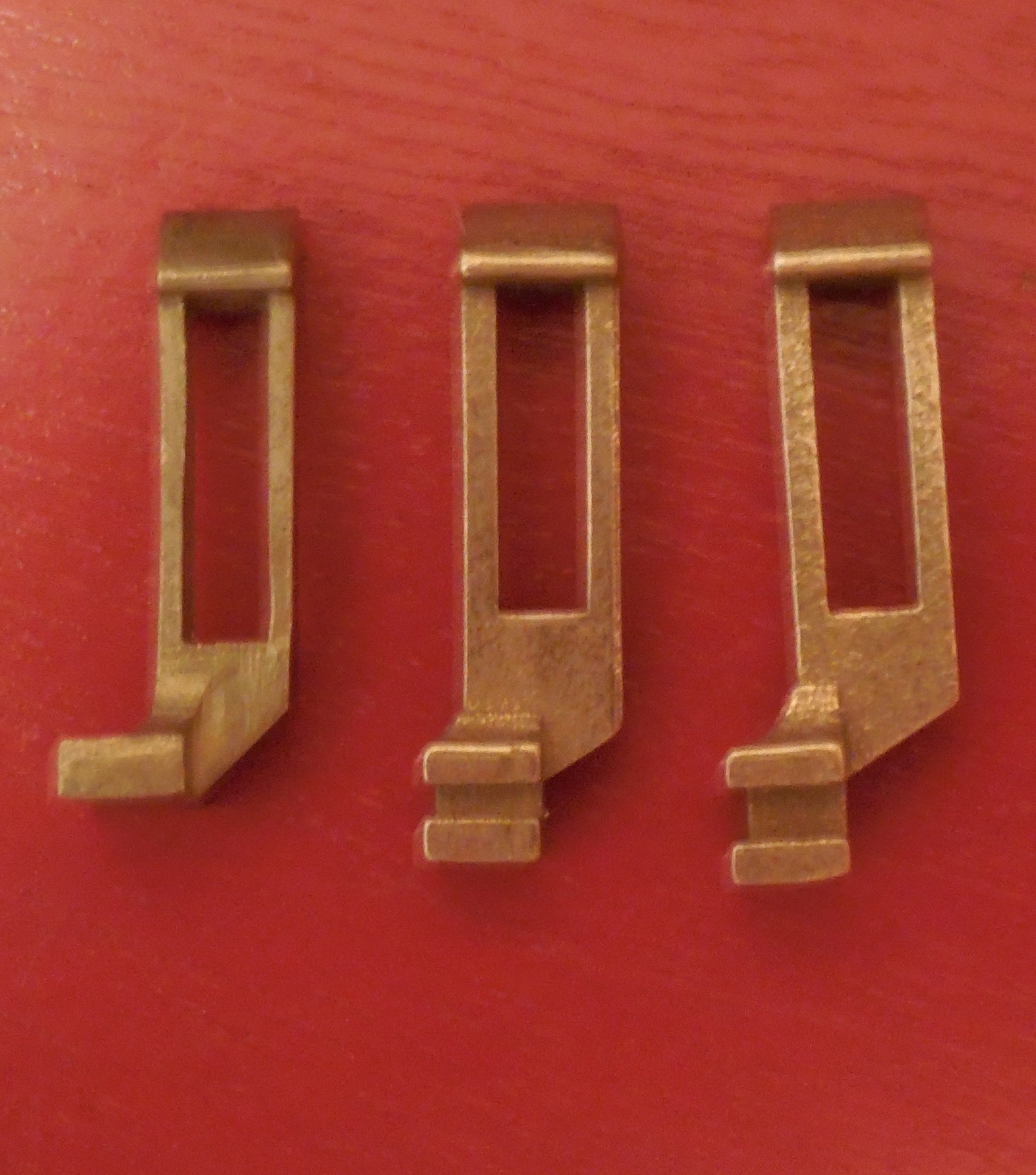
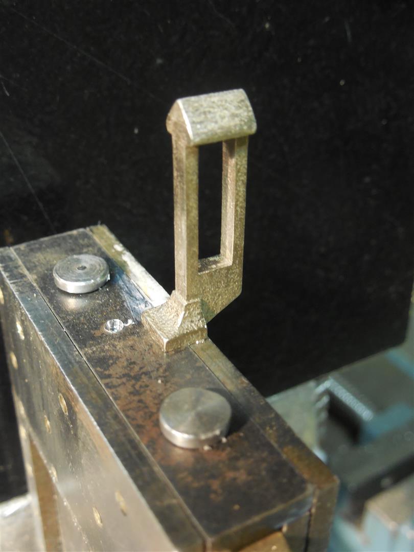
| Now that the outer plates are in place we need to add the spike and hook to the mouton. The spike attachment on the original guillotine is a bit of a mystery since the inside of the mouton has not been examined. The photo on the left shows a few variations on the shape of the spike. One is designed to be attached by screws from the bottom while the two others have a special dovetail base that fits inside the mouton. The dovetail version is the one installed on the photos middle and right. The inside of the mouton is ground out with a Dremel tool to fit the dovetail. |
 |
 |
 |
| The original Berger blade has a thicker section where it is attached to the mouton. This is difficult to replicate in a model. I have used many blades without the stepped thickness but it results in an excessively thick blade so I experimented with grinding a steel plate down to create the dual thickness. I have also replicated the dual thickness by adding a backing plate to a thin blade using embedded screws. On the real guillotine the backing plate was welded to the blade. No matter what design is used the other decision to be made is whether the blade will be hardened and sharpened like a real guillotine blade. Most of the blades I have used are low grade carbon steel which cannot be hardened but a few have been made of hardened steel and sharpened. The blades also have mounting holes with keyed openings matching keyed bolts. The ones shown here are cast from bronze and match #4-40 nuts. |
 |
 |
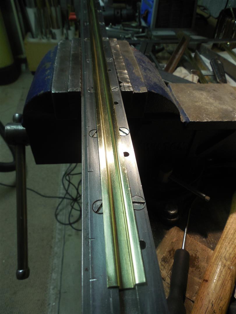 |
| After the mouton is completed the next step is to create the posts and tracks. Here again challenges abound the first one being the tracks. The guillotine has a brass track about 1-1/2" wide by 1-1/2" deep which translate to a 1/4" x 1/4" track in 1/6th scale. While 1/4" x 1/4" miniature brass channels exist they lack the lateral flanges needed to attach them to the posts. I do not believe such tracks are commercially available in any material. For a time I used heavy wall aluminum channels to simulate flanged channels by drilling the side walls to accept long #0-80 screws. Then I resorted to fabricate the channels from screen door frames which are thin gauge aluminum and have an inside width of 1/4". By cutting off the crimped end and bending out the sides 90 degrees to form the side flanges I exactly duplicated the shape of the real track. I still felt that it would be better if they could be made from brass. Above are photos of the latest tracks formed from 20 gauge brass plate bent on a steel form using a vise. This is not a perfect process and it leaves some marks on the completed tracks but my examination of the real guillotine showed that the real tracks were also hand made, with many dents and not perfectly shaped so these small defects are not detrimental to the overall realism of the model. Note that the lateral flanges on these tracks are asymetrical as they would be on the real guillotine. |
 |
 |
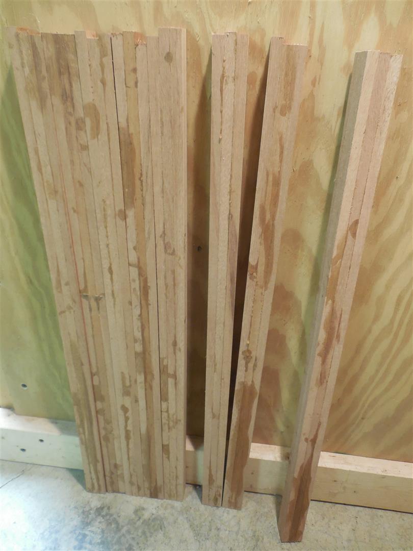 |
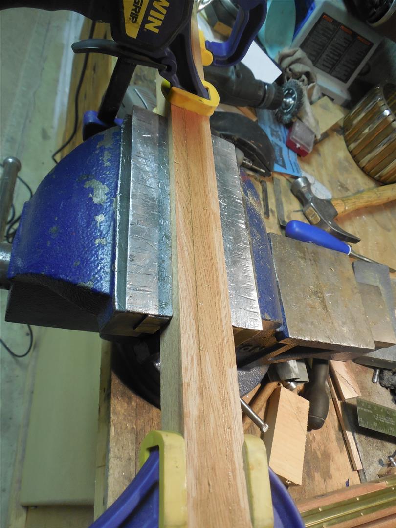
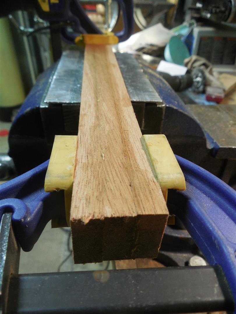
| The posts are very slender for their height. This proportion is often not respected in guillotine models because of the difficulty in fitting all the features and hardware in the small cross section. The thin posts on a 1/6 scale model have a tendency to warp when ambient humidity and temperature change. I use kiln-dried African mahogany for the model. Mahogany has a fine grain which does not stand out when used in scale models. Oak on the other hand has a grain that is very visible and coarse, so it would be detrimental to the illusion one tries to create in scale work. The posts shown here are made from three thin slats of wood glued together. While this is the design of the real posts also, I primarily do this to reduce humidity-induced warpage. When the glue is dry I finish and size the posts with a planer. |
 |
 |
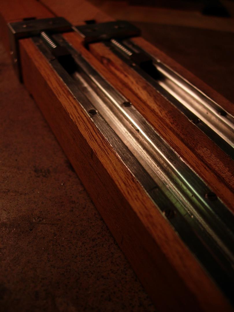 |
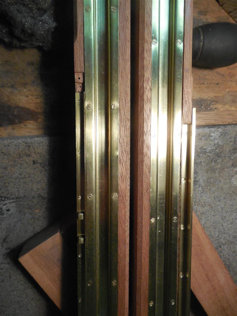
| The tracks are completely recessed into the posts. To do this I router both a deep groove for the main track and shallow side areas for embedding the track flanges. The tracks are secured with small brass or stainless flat head screws, countersunk into the metal. On the St Pierre guillotine each track is secured with 28 screws. On some Berger guillotines - the one from Stockholm and the one exhibited in the MUCEM in Marseilles - there are more screws, from 50 to 90 per track. I use either size #0-80 or #00-90 screws in this application. |
 |
 |
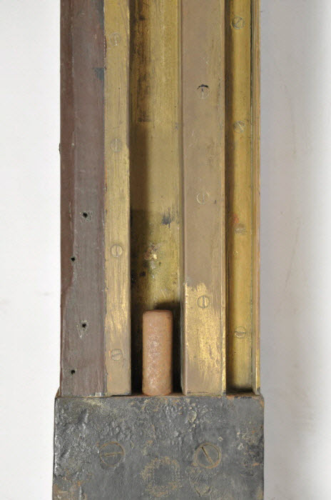 |
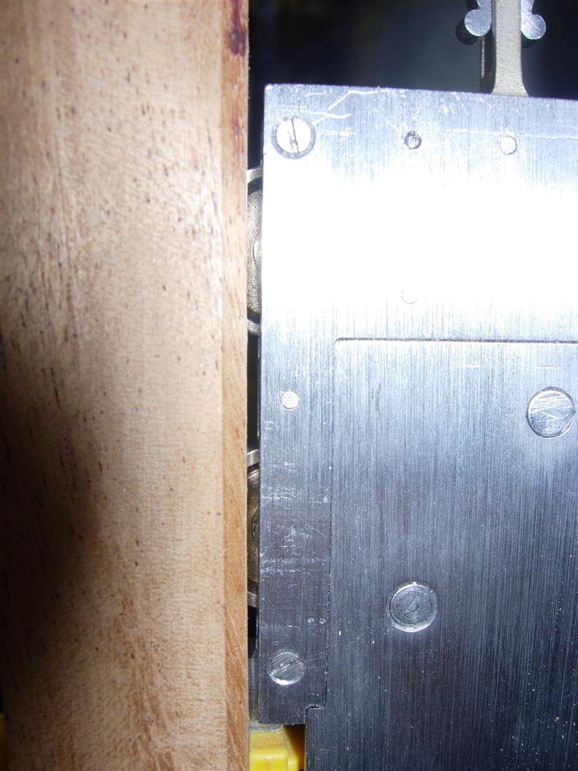
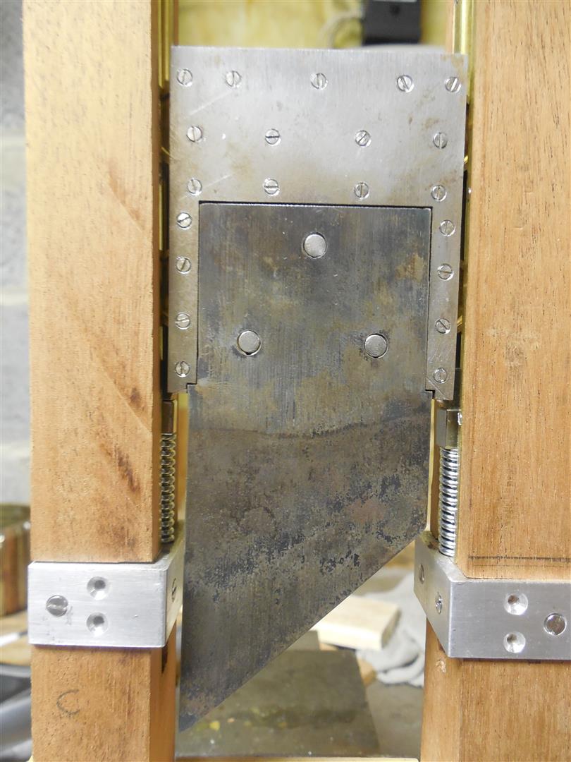
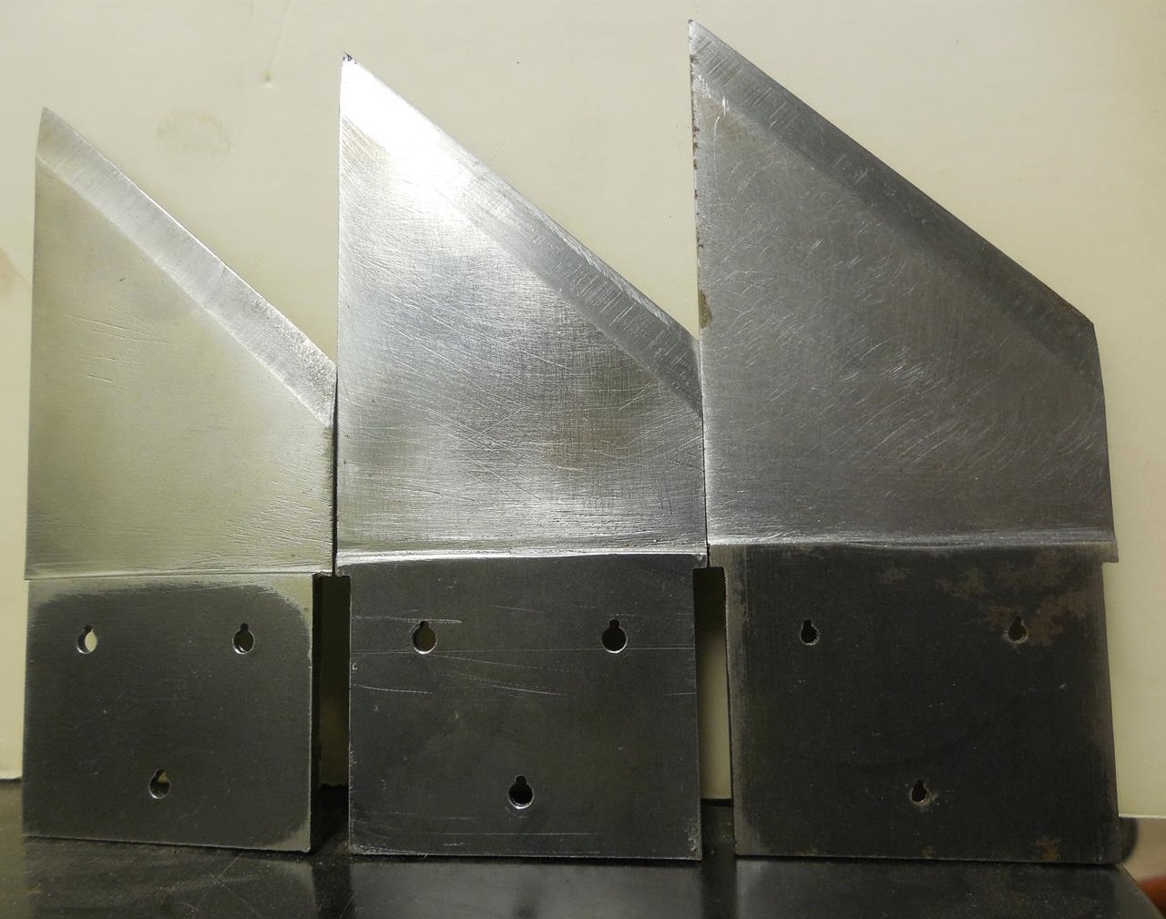
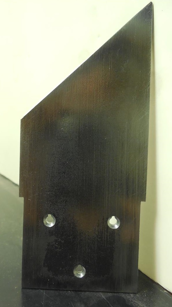
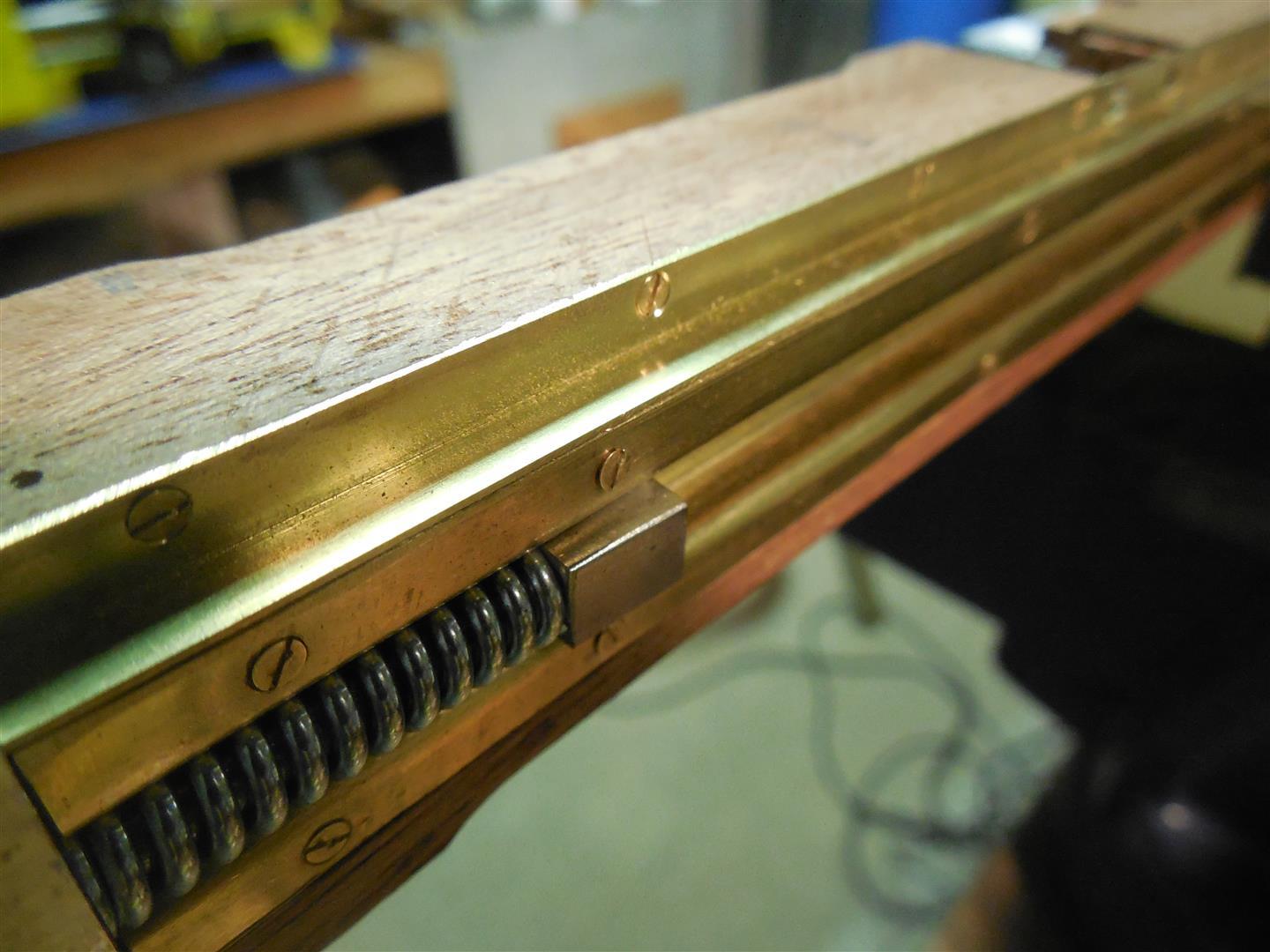
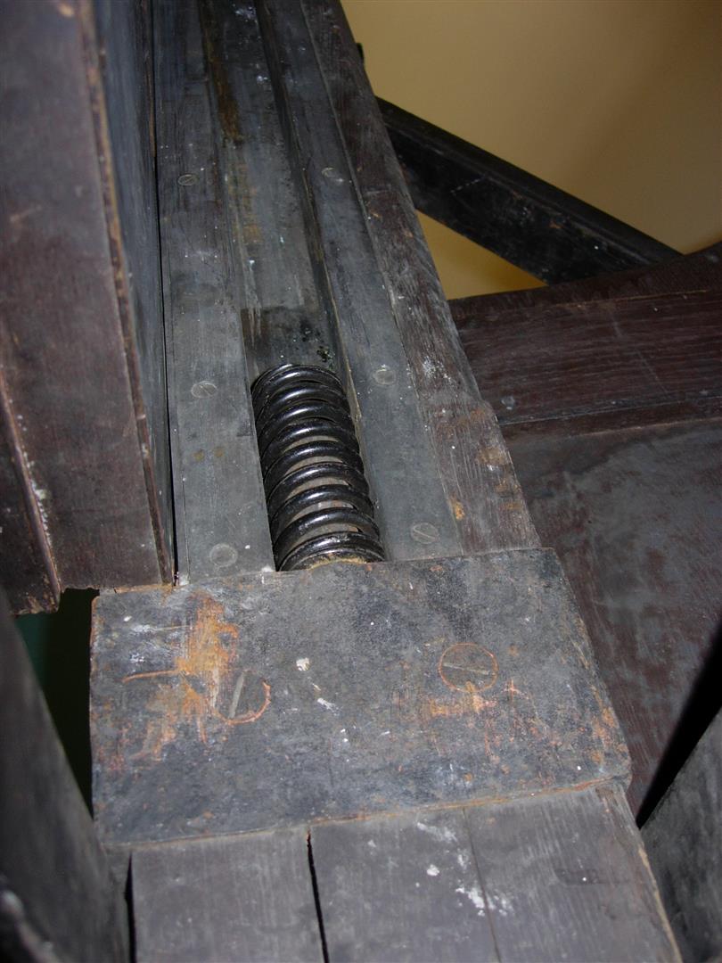
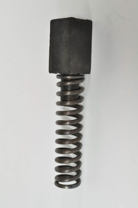
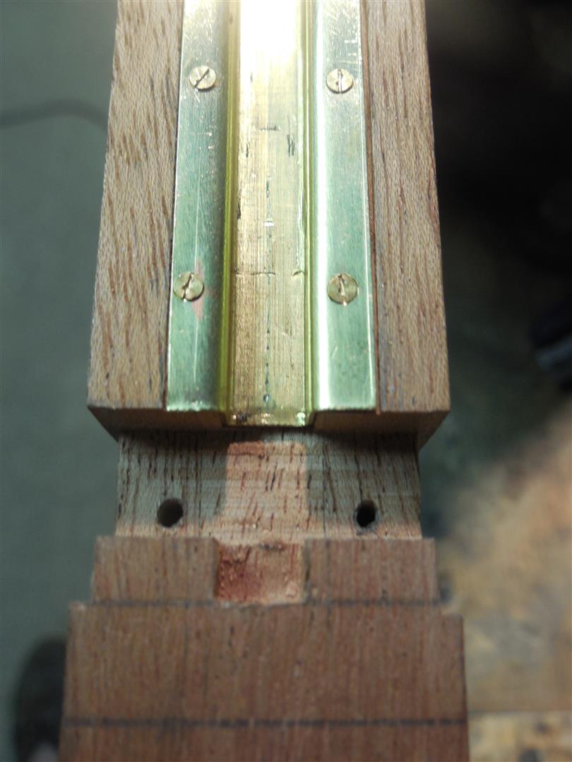
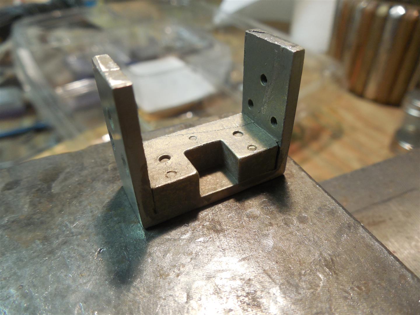
| The lower end of the tracks terminates on a bracket which supports the spring buffers. These brackets wrap around the posts on three sides and are partially embedded into the wood. The top surface of the bracket supports both the spring and the lower lunette. On the real guillotine the impact force from the mouton is truly destructive, so the bracket is forged steel, deeply set in the wood and secured with eight large wood screws. The springs sit on guide pins centered inside each track and are topped with a stemmed rubber cube. This design is not perfect as no springs can absorb the full impact force. They compress fully until the rubber stopper stem makes contact with the top of the guide pin. The rest of the energy is them absorbed in the rubber. As the mouton comes to a stop the springs release their stored energy back into it and cause it to bounce up as much as 4-5 feet. During this rebound the springs can sometimes eject themselves from the guide pins, leading to a much more violent impact on the second rebound. This problem was never fixed on the real guillotine. A late 1940s film of a guillotine demonstration in French Guyana clearly shows that one of the springs bounces out of the track and falls into the head tub. |
 |
 |
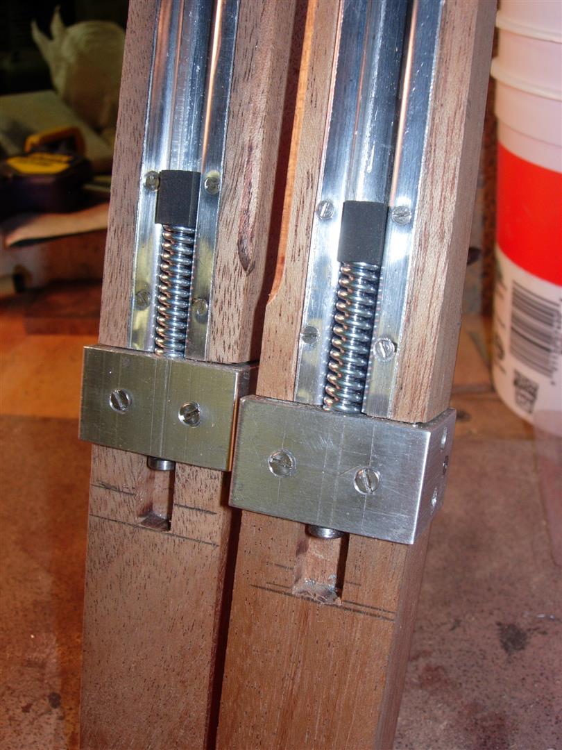 |
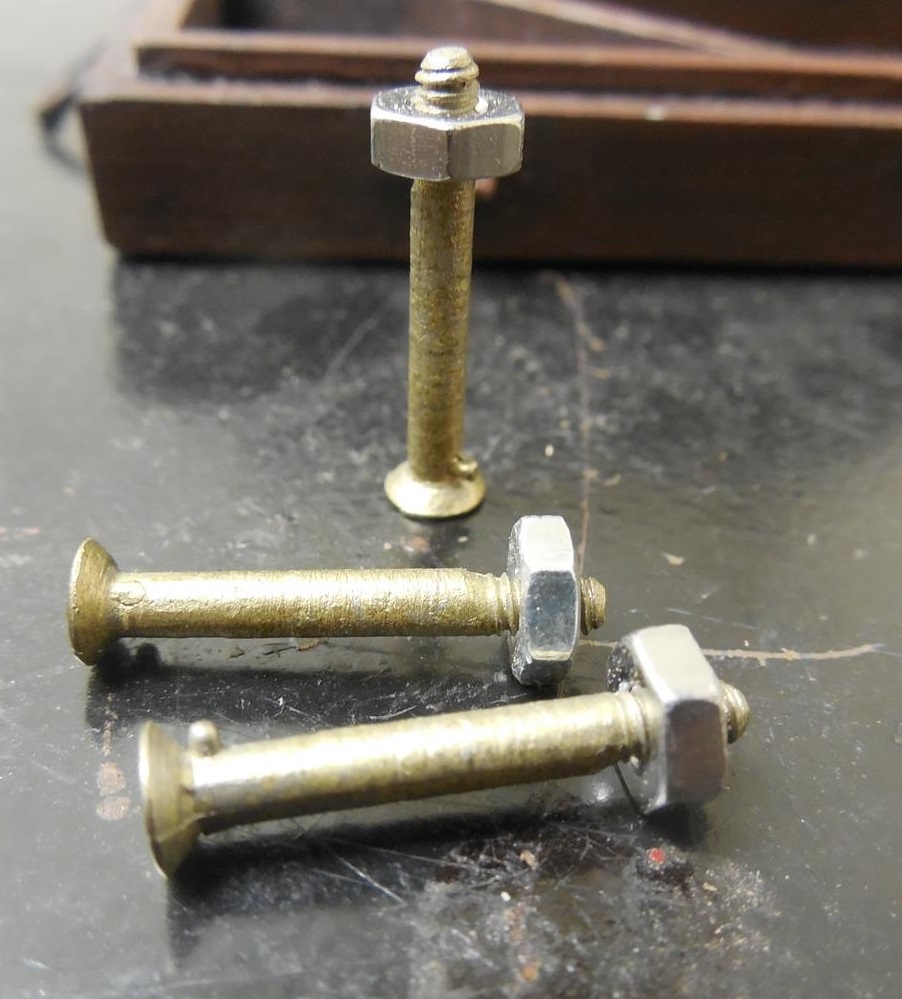
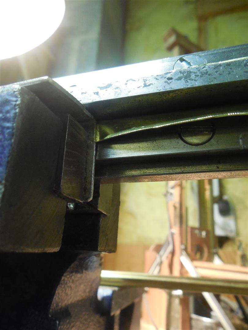
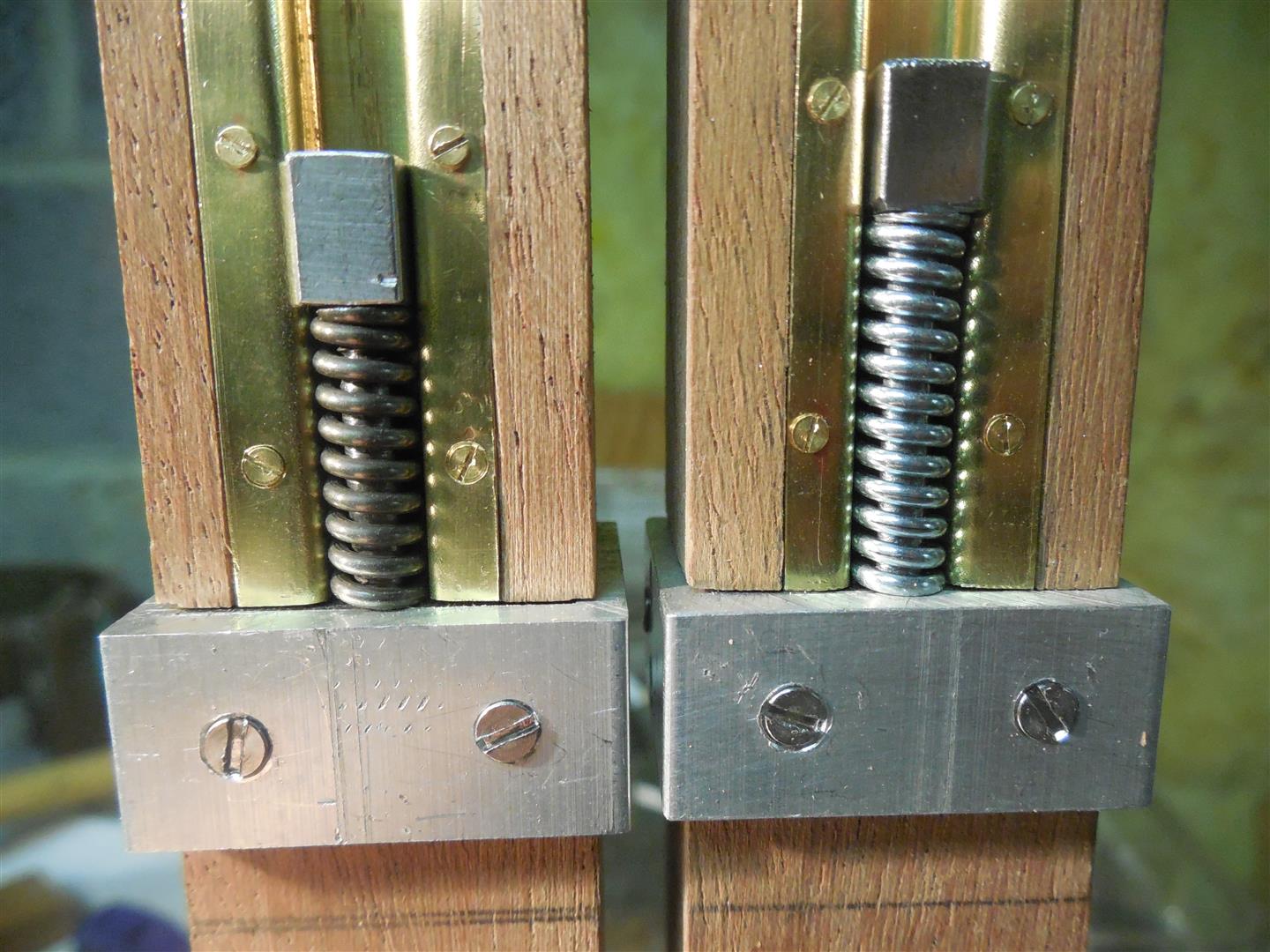
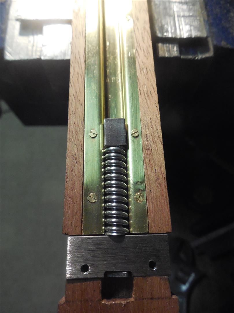
| After exactly duplicating the original design in 1/6 scale I realized that the problems of the original scaled down perfectly on the model. Springs overcompressed and broke and spring assemblies jumped out of the tracks. I first went through a large selection of springs to find the right diameter and length to properly represent the originals and the correct stiffness to not bottom out on impact. The two sets shown here illustrate the solution. The shorter spring on the left, while fitting the model, cannot absorb the full impact force as the one on the right does. The weak springs bottom out and transfer some of the impact force to the frame and support bracket which might cause damage over time. The photos also illustrate how I prevent the springs from jumping out of the tracks. A long guide rod passes through the entire spring length and through the bracket. It is terminated by a small fixed head at one end. On impact it projects into the small cavity under the support. The rubber bumper block on top of the spring is simulated by a steel block threaded unto the other end of the guide rod. The spring is captive and held straight by the rod which guarantees flawless operation. I also experimented with rubber bumper blocks but the material did not survive for more than 200 drops and was prone to deterioration over time when exposed to air and sunlight. I felt that they were not adequate for model longevity. When painted flat black the steel blocks credibly replicate the rubber originals. The photo on the right shows an older model with the rubber blocks and aluminum tracks. Also notable is the support rod that extends all the way through the bracket, leaving the cavity under the rod end visible. On more recent models this cavity is concealed behind the support bracket. |
 |
 |
 |
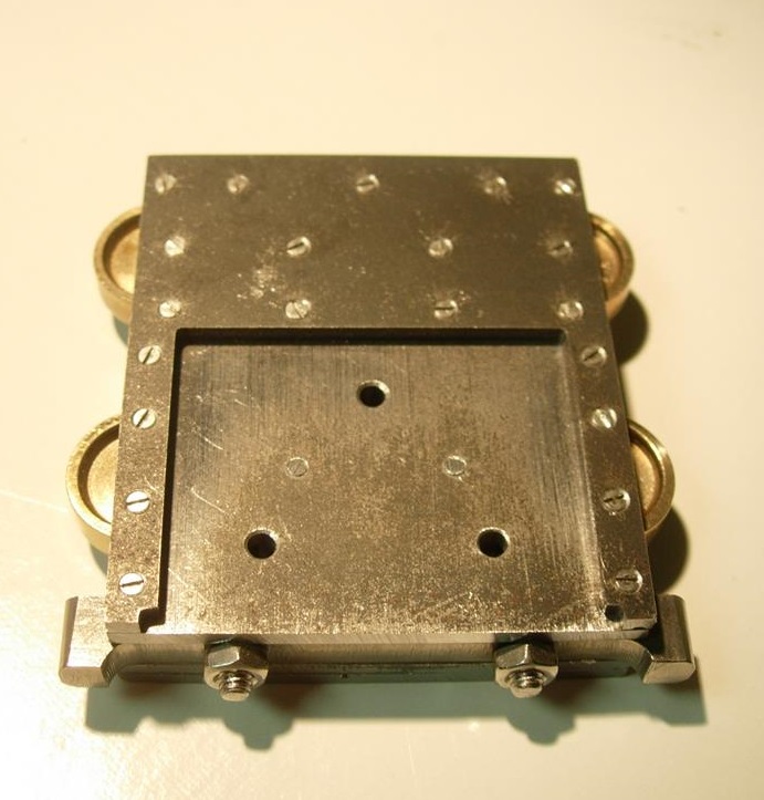
| These photos show how the support/guide rod projection cavity is concealed under the support bracket. On the newest models I have made the cavity an integral part of a one-piece cast bronze support bracket as shown in the middle photo. This is a simpler solution than the two part bracket with the cavity carved into the wood post. Final assembly showing the position of the spring, bumper and bracket under the mouton crash bar. |
| TO BE CONTINUED |