 |
THE SWEDISH GUILLOTINE - 1903 |
|
THE SWEDISH GUILLOTINE - 1903 |
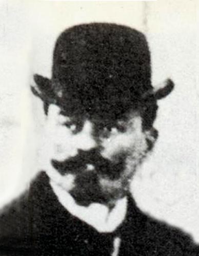
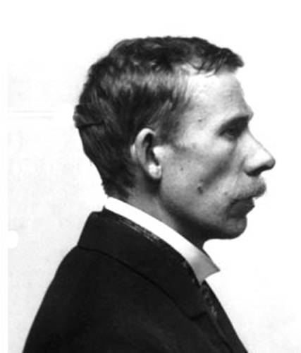
| Sweden adopted the guillotine as the method of execution for death sentences in 1903. Before that year the death penalty was enforced by axe beheading using a low block, but only few people were actually executed (Only 14 between 1866 and 1903). The department of justice did however order a guillotine from the French head-executioner, that same year. Anatole Deibler asked his friend, Marcel Deschamps, architect, officer, professor and sometimes executioner's assistant, to supervise the design and construction of the machine. Deschamps made some minor modifications to the design, eliminating the frame tension rods, in favor of simple spikes in the four corners of the frame. He also dropped the hinges on the front and rear braces and added double-bolted connections at those locations. Otherwise his guillotine is undistinguishable from the 1872 version. On November 23, 1910, the guillotine was used, for the first and last time, to execute convincted murderer Johan Alfred Ander at Langholmen prison in Stockholm. He was the last person executed in Sweden. The pictures below are a series of comparison shots between a 1/4 scale version of the Swedish guillotine and the real one. This is done both to explain the construction of the real machine and to showcase the accuracy of the scale copy. The photographs of the real machine are taken at "Nordiska Museet" in Stockholm. |
 |
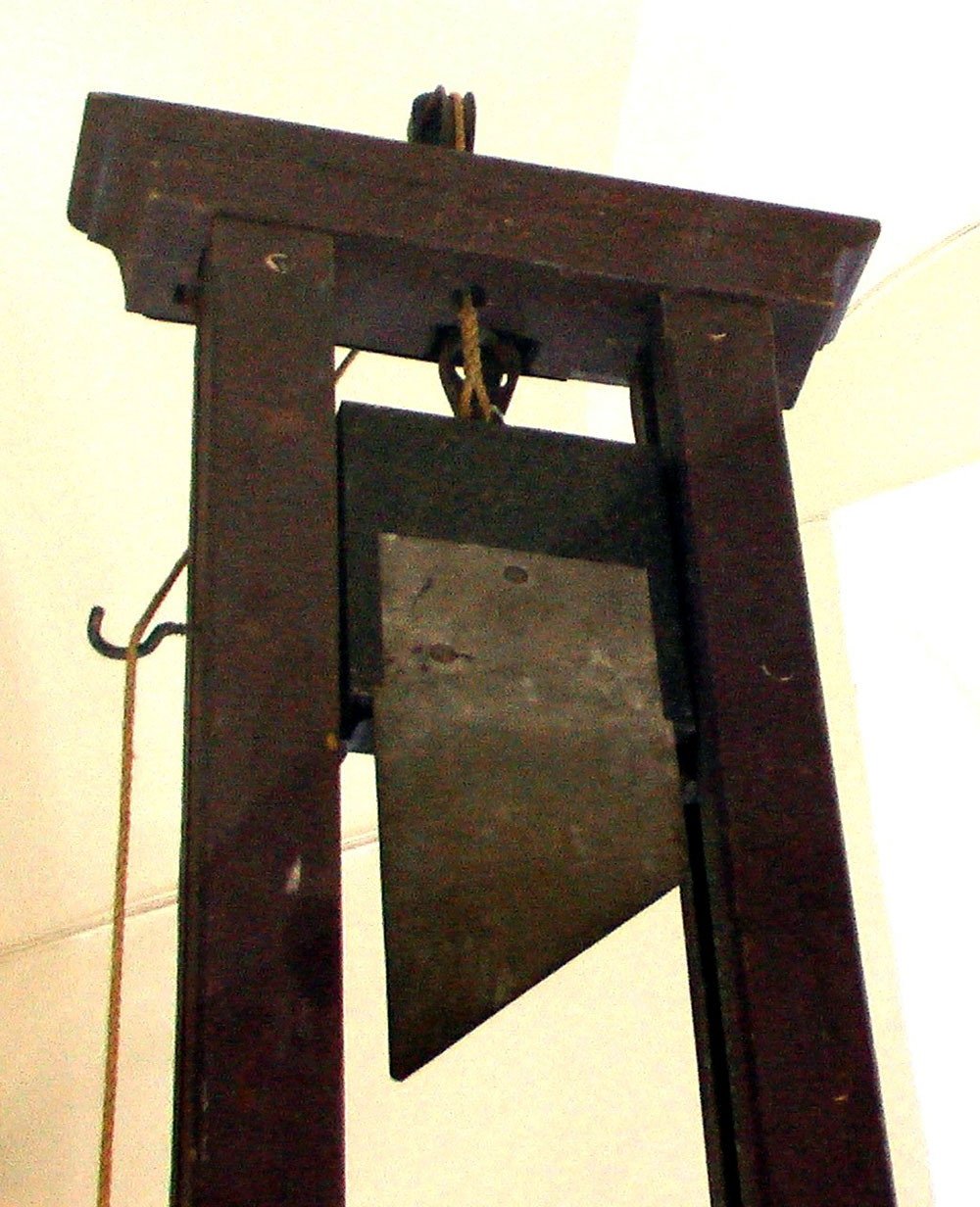 |
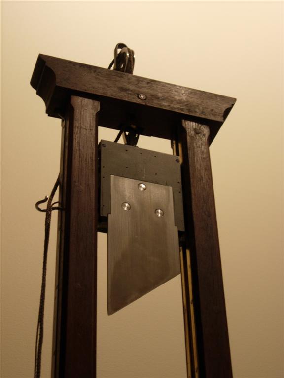
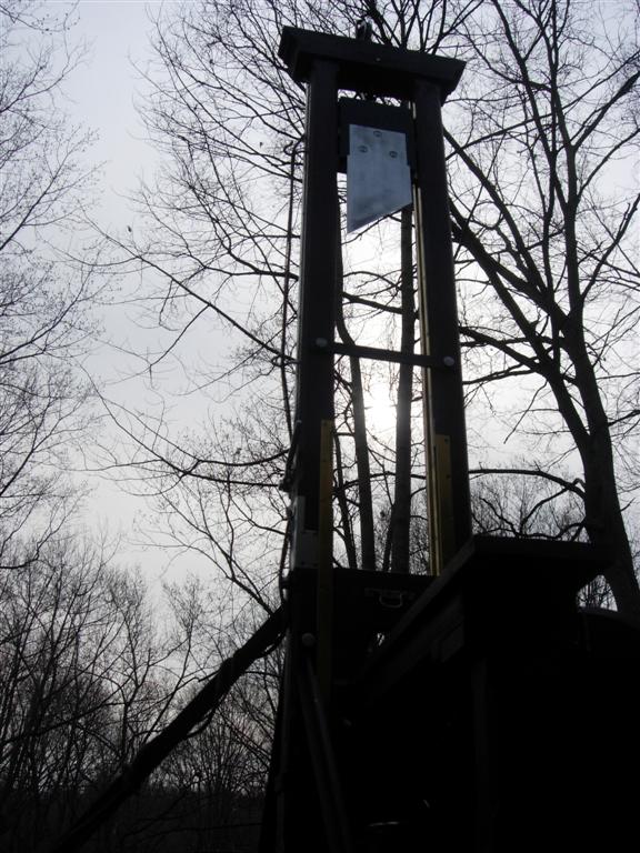
| This shot shows the blade and chapiteau (Top crossbar) from the condemned man's point of view. On the right side is the 1903 Berger guillotine from Sweden and on the left is my 1/4 scale model. Although the guillotine was designed to be a very humane execution device, it still elicited incredible fear and respect among it's victims. According to the writings of several of the famous French executioners, the criminals were almost always drawn to stare at the blade as they approched the machine, some freezing in fear, some resisting violently and some collapsing and passing out. These incidents prompted Nicolas Roch, the head executioner of France from 1872 to 1879, to add a wood shield in front of the blade to hide it from his "customers". This "improvement" was undone by Louis Deibler who followed Roch in the job. The picture of the model shows the rope designed to raise the blade and the top hook used to store it. The spike protudes from the top of the mouton and is firmly held in the steel jaws of the release mechanism and the top of the pulley can be seen above the chapiteau. The mouton of the real machine weighed 35-40 kg and the blade with its three bolts around 10-12 kg. On the model the complete assembly weighs over 4 Lbs. |
 |
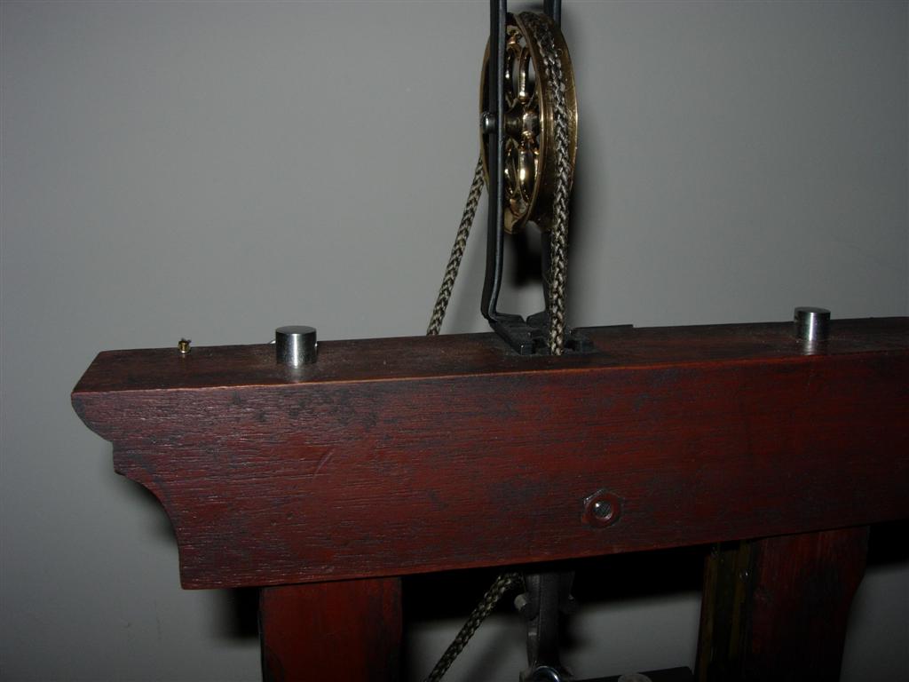 |
| Here is another pair of photographs showing the 1903 Berger guillotine from Sweden and my 1/4 scale model. This is a view of the top of the chapiteau with the pulley and the bolts. The specially designed bolts with the "cheese box" head were used on all Berger guillotines except the 1868 model, which had square-head bolts. A steel rod was inserted through the hole in the head of the bolt to tighten or loosen it. As can be seen in the photos the bolts used on the chapiteau had taller heads than the ones used elsewhere on the machine. The model bolts are made from regular hex-head machine screws that are first drilled then turned on a lathe. The rope on the real machine is not of the proper design. It is too thin and lacks the metal 8-ring and tether string used to pull it free of the mouton hook. The chapiteau of the real machine was made of several pieces of wood glued or bolted together. Likewise my model chapiteau is laminated from two pieces of mahogany. |
 |
 |
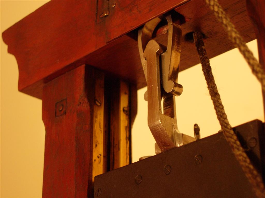
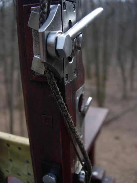
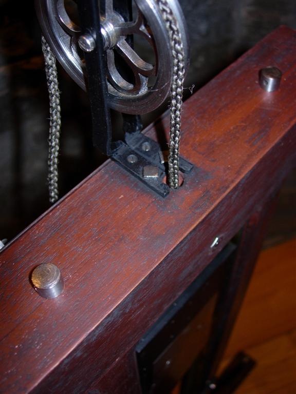
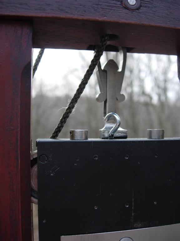
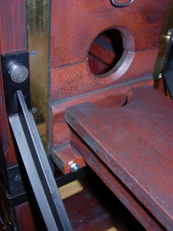
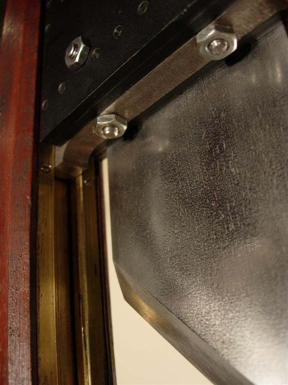
| These two pictures show a close-up of the claw and spike mechanism that holds up the mouton and blade. On the real machine, the claw has been wired shut as a safety precaution. Behind the spike, the hook, used to attach the rope, is visible. The lower edge of the hinged sheet-metal door that covers the mechanism compartment can be seen at the top of both pictures. To the left of the model picture one can see the brass track, which is dark with corrosion and dirt on the full size counterpart. Also visible is a square steel nut embedded in the wood. The real guillotine uprights are made of three nearly equal thickness oak planks bolted together with eight embedded bolts each secured with square nuts on the back side. This construction was copied exactly for the model. The heads of the bolts are countersunk into the posts, covered with a wood plug and painted over. This is somewhat unique to the Swedish guillotine, as the bolt heads are exposed on most of the French guillotines. |
 |
 |
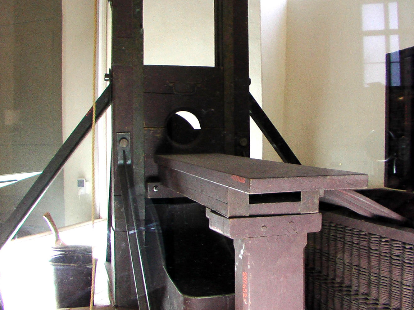
| These are taken from the back side of the machine, showing the lunette, T-braces and the shield. The real lunette is lined with brass, which has oxidized and taken a green-grey color barely distinguishable from the rest of the machine. My model also uses a brass liner secured with miniature steel screws. Even the pattern and number of the screws matches the real one, albeit from the St Pierre guillotine which I have been able to examine closely. The rear T-braces and their cheese-box head screws are visible on both photos. On the model the blade spring stop, with the rubber cube bumper is visible, while it is lost in the shadows on the other picture. The photographer's shield on both the model and the real machine are hinged so they can be folded flat for transportation. |
 |
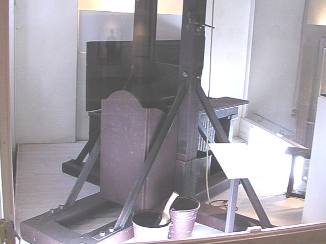 |
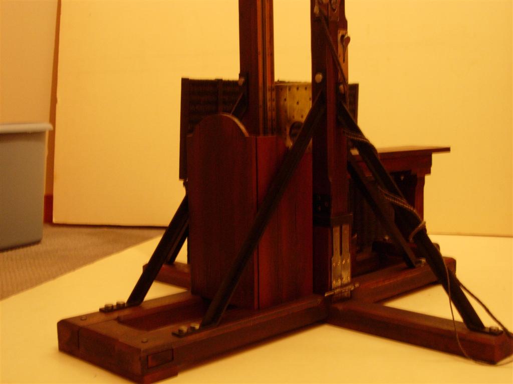
| A side view from the rear of the machine, shows the position of the photographer's shield and the overall proportions of the machine. The braces on the model are made from steel plate and screwed together by drilling and tapping the web of each tee in 7 or 8 places. Unfortunately, there are no commercially available steel tee bar that would fit the scale of the model and precision-welding the two tiny parts together is way beyond my pay grade. |
 |
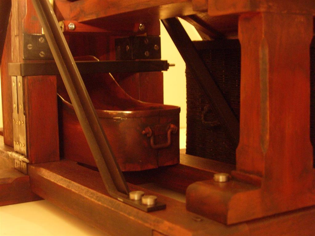 |
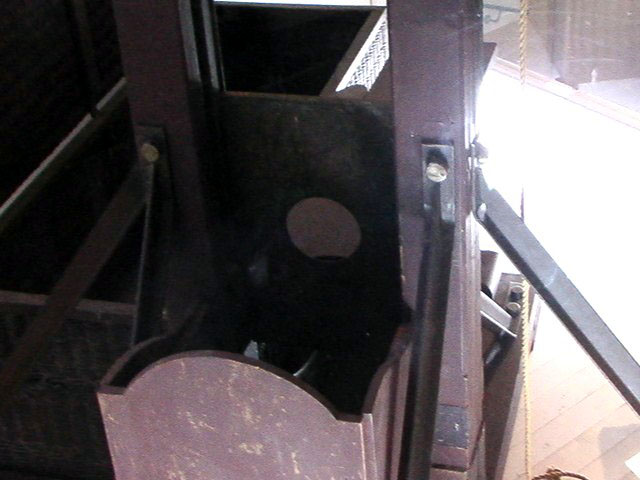
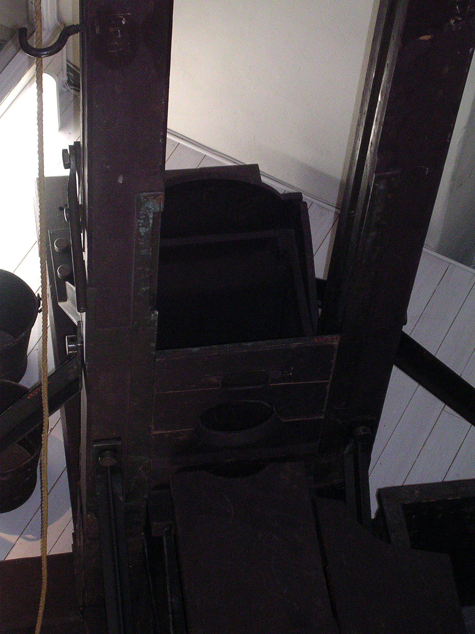
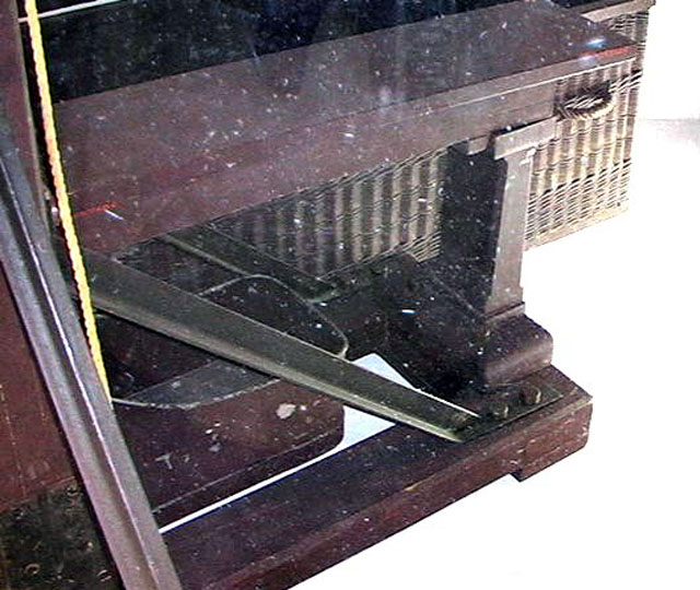
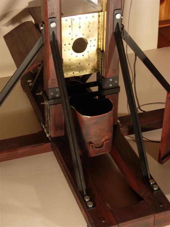
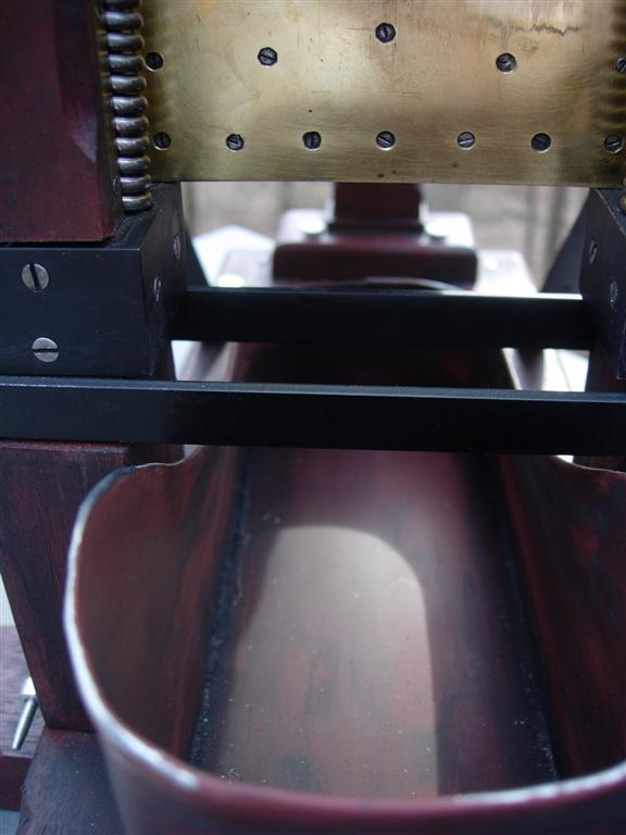
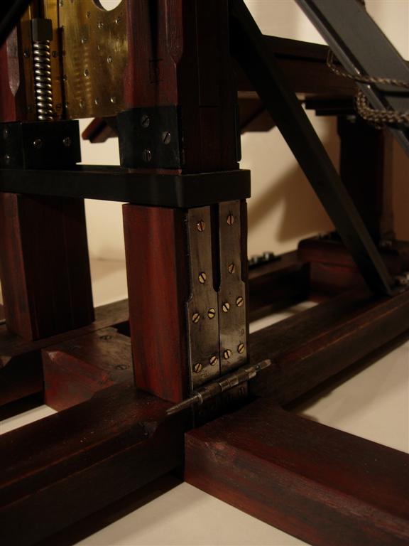
| These views from underneath the bascule show the bucket that was used to catch the severed head and any spills from the execution. On the real machine, the C-brace, that holds the posts together, is missing and consequently the bucket has been pushed too far back. With the brace in place, as seen on the model, only the low part of the bucket can be pushed beyond the uprights. On both pictures, the post hinges can be seen in the lower left corner. The model duplicates the dual hinge design of the real machine, which is also a feature unique to this specific guillotine. Older Berger guillotines utilized a single wide hinge. |
 |
 |
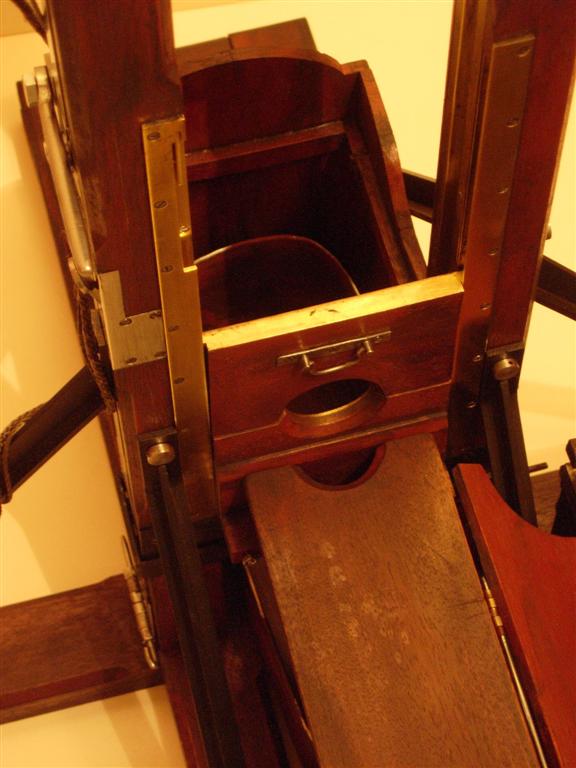
| These plunging views highlight the lunette assembly with its swivel handle, brass tracks, and complex release mechanism. The opening at the upper end of the left track cover allowed the lunette boards to be installed and removed from their track with the uprights in place, this in order to facilitate assembly and disassembly. A removable locking bar was installed to prevent the executioner from inadvertently raising the upper lunette too far and pulling it out of the track. I have copied this feature for the first time on this model. |
 |
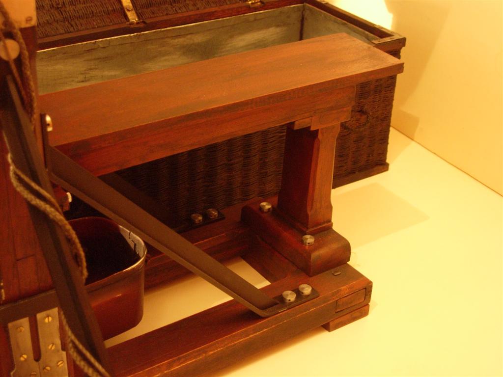 |
| Another pair of views of the area under the bascule where the position of the bucket can be seen. Also a clear view of the rear bascule support and the T-braces. Note the two bolts securing the rear brace to the base frame. These double-bolts are a feature unique to the Swedish Berger machine and not found on any of its French counterparts. |
 |
 |
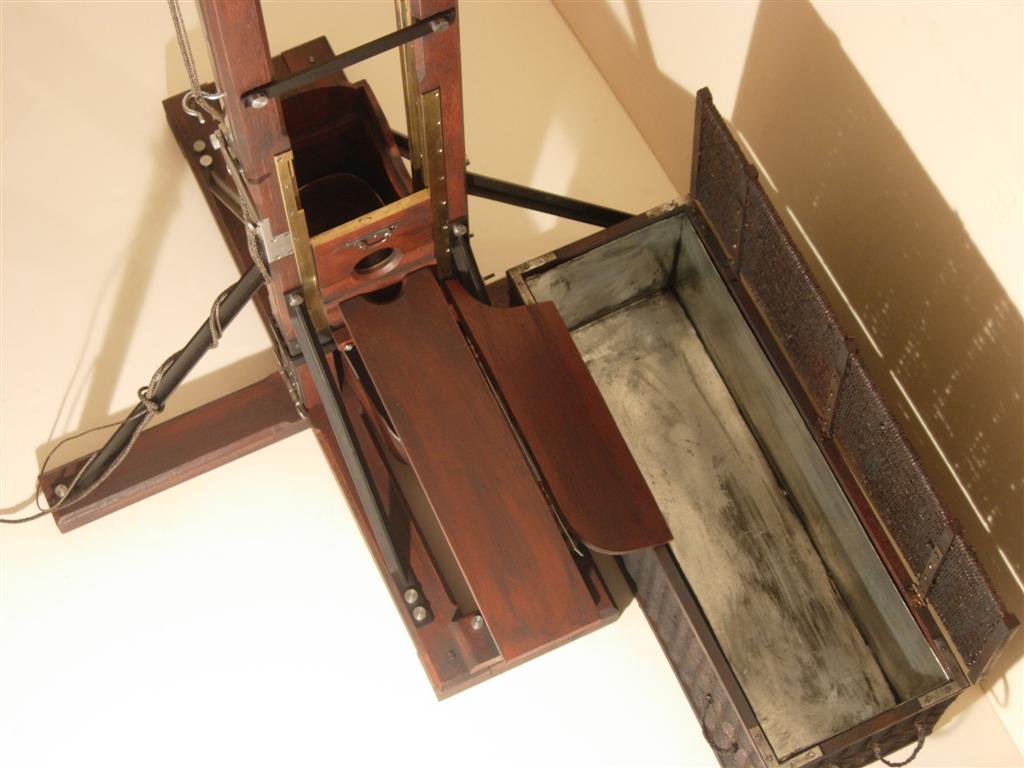
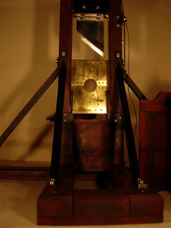
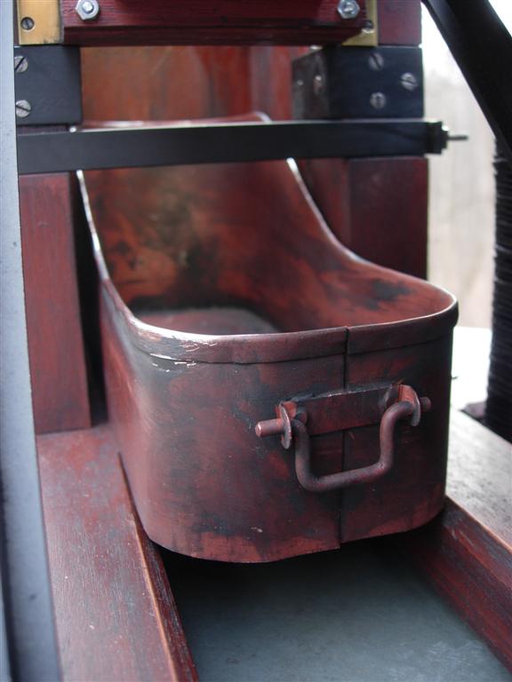
| A good bird's eye view of the two machines showing the inside of the body basket. The zinc liner is visible inside both baskets. The metal cross brace spanning the uprights is seen on the model, above the lunette but was forgotten on the real machine. Note the two water buckets beside the real guillotine, used to wash down the machine after the execution. |
 |
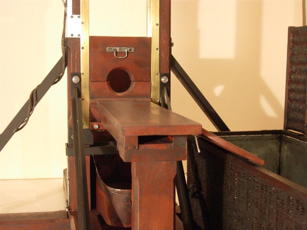 |
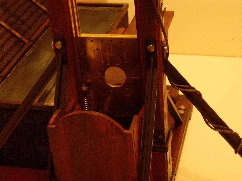
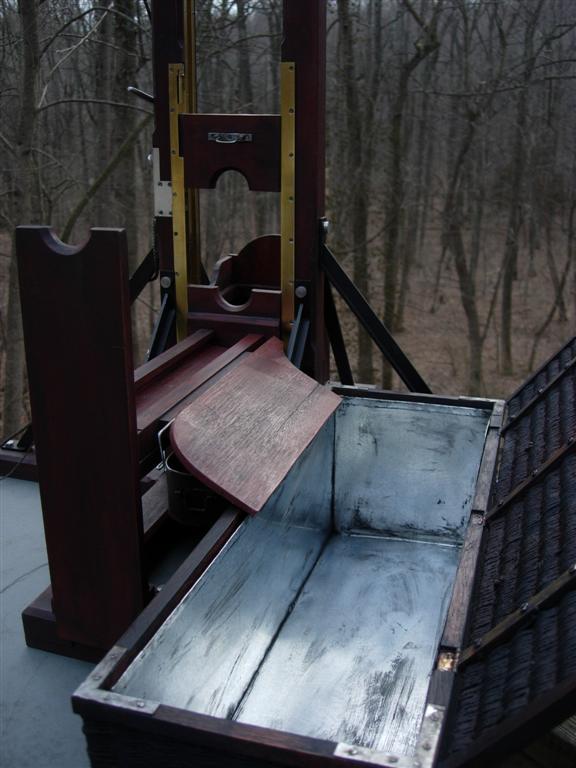
| A pair of photos looking at the front of the lunette show the bascule plank and cradle, the T-braces, the uprights with the lunette locking mechanism embedded in the left one, the side board hinged from the right side of the bascule and sloped toward the basket. The lunette-release mechanism on this model is a self-contained assembly mounted inside the angled cover plate. It comprises a lever with a pivot axle, a C-shaped slide, a connecting rod, two guide bars, a retainer plate and a pair of springs mounted on guide pins all this housed in a cut-out on the side of the upright. The model is finished with red-brown paint, clear linseed oil and then "aged" with a flat black paint wash. The real machine was completely painted with a reddish-brown oil paint, which has faded to a greyish-purple over the years. |
 |
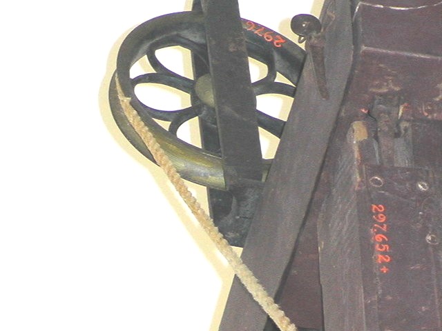 |
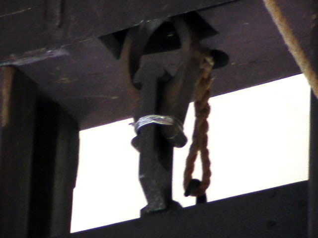
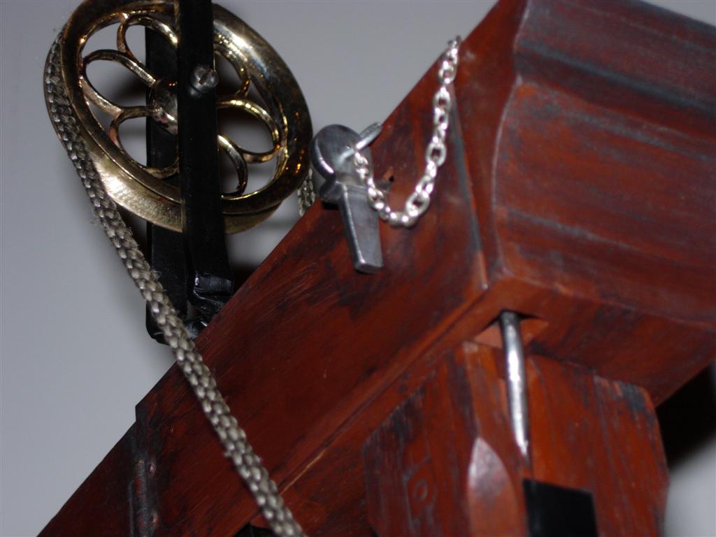
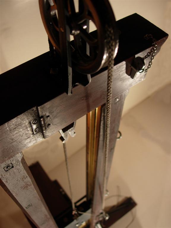
| This pair of photos shows the pulley from the side and the mechanism door with its locking pin. The pulley on all Berger guillotines was of the design seen here with six, petal-shaped, spokes and a wide gutter-like groove. This model utilizes a custom-cast hand polished bronze pulley made to closely resemble the real one. The frame that holds the pulley is formed from a single piece of flat steel bar folded in five places to make the mounting tabs as well as the arch. I was able to replicate the real design pretty closely on the model. Note the release pull rod entering the underside of the chapiteau in the foreground. |
 |
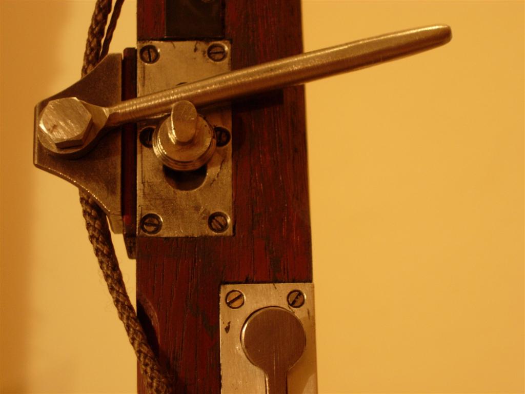 |
| Here is a side view of the release lever and of the top of the lunette lock pushbutton. The lever on the real machine on the left is drooping because the pull rod isn't connected to the mechanism in the chapiteau (for safety reasons). The model shows the normal position of the pull lever when it is connected. Note the round hole under the lever pushknob. This enlargement in the guide slot allows the pushknob to be uncrewed and removed when in the lower position. The entire lever assembly can also be removed by taking out the two square-headed bolts and the lunette pushbutton can be depressed and locked in place with a set screw to keep it flush with the cover plate surface. Along with the removal of the two rope storage hooks, this left the upright devoid of any protrusions so it could easily slide into a narrow storage compartment under the fourgon. |
| Below are a few additional photos of the model for which I have no counterparts showing the real machine. Click any picture for an enlarged view. This is the largest and most accurate guillotine model I have built. For an idea of the actual size of the model click here. |
 |
 |
 |
 |
 |
 |
 |
 |
 |
 |
 |
 |
 |
 |
 |
 |